Where is the Continuity Setting on a Multimeter

Are you confused by all the symbols on a multimeter? Are you wondering what that little line with a squiggle next to it could possibly mean? Perhaps you're still learning how to use your multimeter or maybe you've had yours for a while, but are just unsure on what a couple of the symbols actually mean because you've never had to use that setting. This guide is for you. We're going to explain in detail what settings and symbols mean on the common meter.
The last thing you want when troubleshooting an important issue with your digital multimeter is to misunderstand what the reading means. This could be especially dangerous if you were trying to undertake a continuity test and accidentally had your instrument set to the Volt measurement.
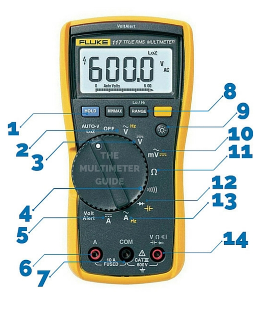
In our guide we're using the Fluke 117, we chose the Fluke because they're a great all round multimeter and they have the symbols and settings that you'll find on 95% of the multimeters on the market. Take note of the yellow symbols around the dial, these readings can only be performed after pressing the SHIFT button. The SHIFT button works the same as on a standard keyboard, you simply press it and the meter will perform and additional function, depending on where you have set the dial.

Number 1: Hold Button. This button will "hold" whatever the meter reads after you have pressed it. This is a great feature if you need to remember the exact reading of what you're measuring or if you cannot see the multimeter whilst you're testing with the test lead or probes
Number 2: AC Voltage. This will be your most common setting for testing voltages around the home or work. Depending on where you live, you will typically measure between 100-240 volts AC.
SHIFT: Hertz. Used to measure the frequency of your circuit or equipment. Different equipment and circuits are designed to operate at either fixed or variable frequency, so it's important you know that before you undertake your test.
Number 3: DC Voltage. The DC Voltage setting will enable you to test small electronic ciruits, indicator lights and batteries. 99% of the time you come across DC Voltage, it will be below 30 volts DC.
Number 4: Continuity. The meter will emit an audible tone when continuity is detected between two points. This is a fast and effective way for finding short circuits, or open circuits. Simply place one probe on one point, and another probe on another point and and your meter will give you a visual and audible signal.
Number 5: Direct Current. The same as Alternating Current (Number 13), but with Direct.
Number 6: Current Jack. Only to be used for measuring current amps with either a red test lead, or a dedicated clamp attachment. If you use a dedicated clamp meter, you will most likely not have this jack on your unit.
Number 7: Common Jack. Used for all tests and is only to be used with the black test lead.
Number 8: Range Button. Used to cycle between different ranges of your meter. Most meters have auto-ranging, but some have the option of selecting a specific range. For example, you may want to know what your Ohms reading is in mega-ohms.
Number 9: Brightness Button. Cycles the backlight of the display from dim, to bright.
Number 10: AC Millivolts. If you're testing a small ciruit on the AC Voltage setting and the reading is low, it's advised that you switch to the AC Millivolts setting to obtain a more accurate reading.
SHIFT: DC Millivolts. As above, but with DC voltage.
Number 11: Ohms. This setting is used to measure the resistance, which is measured in ohms. The function on its own is called an ohmmeter. A great way to check the accuracy of your multi meter is to get a resistor that you know the resistance of, and use the ohms setting to test the resistance. If it reads correctly, you can be sure that your DMM is accurate. The ohm setting also a quick and easy way to test the condition of fuses - if the meter reads OL, the you can be sure the fuse has blown. SAFETY NOTE: only test fuses with the ohms setting when they are OUT of the circuit.
Number 12: Diode Test. The diode test setting is the most reliable way to test if your diodes are good or bad. The other way to test if a diode is functioning as it should involves using the Ohms setting, however it isn't as accurate as using a dedicated diode test.
SHIFT: Capacitance. It is extremely important to note that some capacitors will have an electric charged stored in them, even after power has been turned off. Please ensure you safely discharge capacitors before measuring their capacitance.
Number 13: Alternating Current. Normally performed with the addition of a clamp attachment, the alternating current test is a must for tests such as how much load an appliance is drawing.
Number 14: Red Jack. Used for all tests besides current, including: voltage, resistance, frequency, diode, duty cycle, temperature, impedance and capacitance.
We hope that you have found this guide useful. Having even a basic electrical knowledge and your own testers will help you greatly, and could save you thousands of dollars in electrician costs. In saying that, voltage and current can be extremely dangerous - even at small measurements, be sure to call an electrician if you have any doubts and never carry out any work that requires you to be licensed.
Source: https://www.themultimeterguide.com/multimeter-symbols-guide/